Senior Lab Experiment: Laser Diode Spectroscopy#
Structure of this lab:#
You are given a set of instruments, which include 90/10 and 50/50 beam splitters, total mirrors, photodetectors, and an IR external cavity laser.
Goal:#
To observe the Doppler-Free Spectra of Rb gas cell.
To observe the degenerate ground states and the excited states of the Rb Spectra with different isotopes.
Key to finishing this lab:#
Tune the laser to the right mode.
The piezo is just used to sweep the laser like a small little jitter with a triangle wave AC signal.
Play with the DC signal more to get it to lase at the right mode.
Just that the laser could be lasing consistently does not mean it is properly optically pumping the Rb gas cell. Make sure you are lasing at the appropriate wavelength of the different isotopes of Rb, this is why you need to sweep with Piezo!
What is the band gap energy of the Rb85a/b and Rb87a/b? What wavelength are they?
Once you have tuned the laser to the right mode, you’re 75% done with the lab. You need to ask yourself why you need to optically pump the cell, and why does optically pumping the cell result in certain excited states dropping the
Trust in the process, I spend much more time talking about the laser for a necessary reason. If the laser is analogous to a key, and the experiment is analogous to a car, you cannot run a car without the right key.
The most important part of this lab is to know what mode the laser is operating at. Without an optical spectrometer, you don’t know what wavelength the laser is lasing at. Once the laser is operating, then the spectrum will show up, puzzling out the schematics and optimizing the test bench would be much more manageable.
Making Physics Lab Manual more comprehensible and accessible to students:#
Here is a quick outline of topics for what needs to be covered to complete this lab.
How to work with the experimental setups
What kind of physics are we probing?
Can we understand the physics with the mathematical models/derivation that we know?
How does this laser work?#
As provided by the lab manual, the laser model TOLD9200 is a gain guided laser diode (gain will be discussed in later section), with the diode itself being an edge emitting laser (where light exits from the sides of the epitaxial wafer), and the external cavity forms between the laser and the Bragg’s grating. See Fig. 11 for an image of the wafer, which shows the laser diode itself, made out of crystal grown epitaxially.
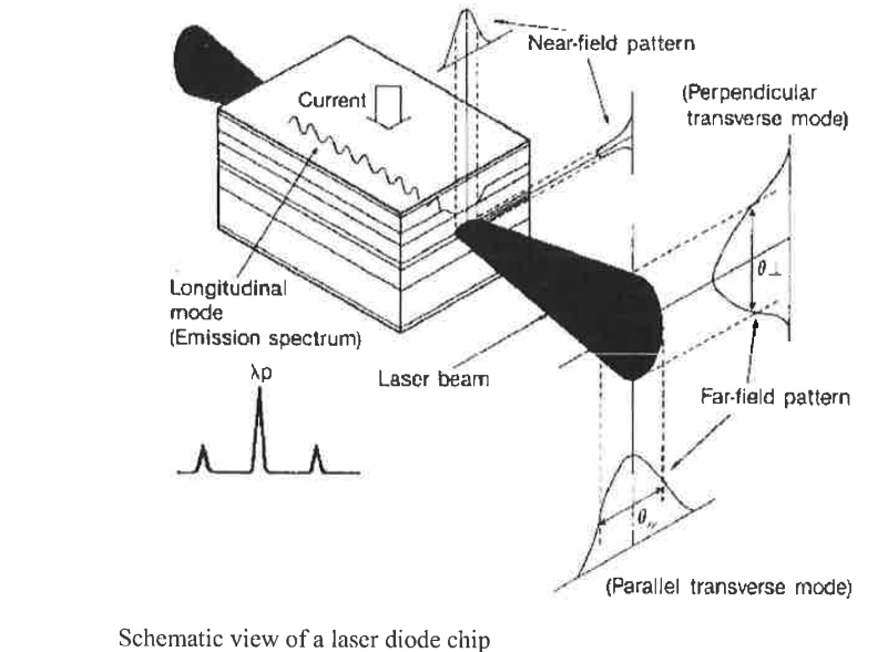
Fig. 11 A picture denoting the properties of a gain-guided Edge Emitting Laser.#
The laser stage of the experiment/schematic is not to be adjusted too much except to tune the injection current and voltage inputs. Depending on the setup of the lab, set up the power supply and to a 10mA:1V ratio for better control. The external cavity is also optimally positioned at a particular angle for ideal mode. Refer to Fig. 12 for an image of the whole laser stage.
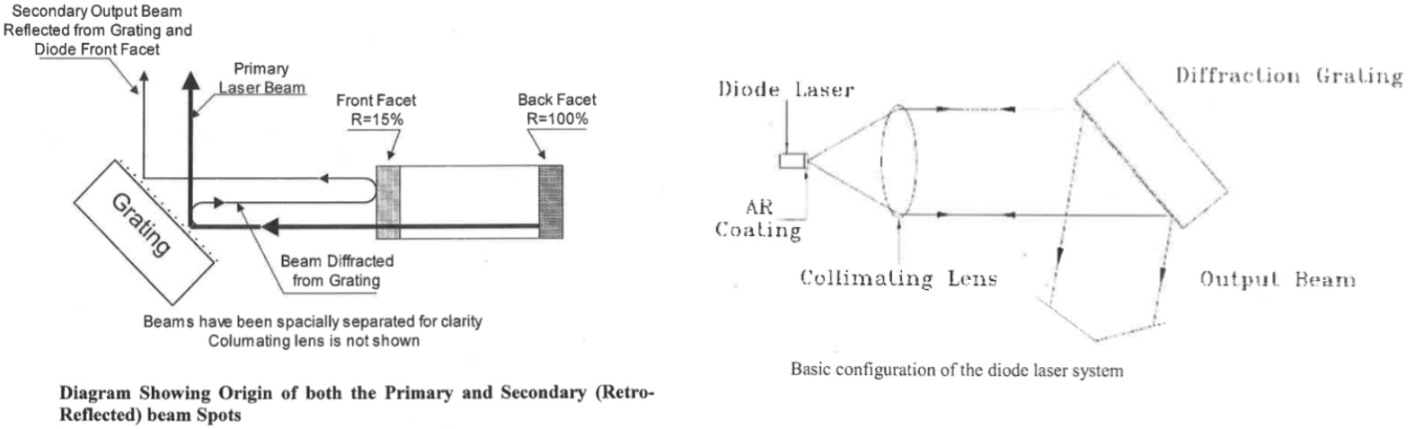
Fig. 12 On the left is a ray diagram denoting the primary and secondary laser beams of different optical paths. A quick note, the laser has an internal cavity on the edge of the wafer, formed by reflective coating between the front and back facet, as seen in Fig. 11 along the direction anti-parallel to the light ray, also known as the internal resonant cavity. The left graph is also to add a bit more context as to why you could see split peaks or double peaks. On the right is the full laser stage, also including the collimating lens, which works to converge the diverging light ray onto the grating feedback.#
Now that we have briefly established an idea as to how the laser works and the functions of each individual component, we can discuss the operation of the laser.
What is “gain” for a laser?#
In this lab, having an experimental intuition on gain is extremely important![1] This is essential in getting the laser to lase in the desired mode. While mode hopping is a phenomenon with many attributes, this experiment has two primary attributes, the external cavity and the injection current. Temperature is omitted since it is held at a constant 50˚C. [2]
A pictorial definition from the lab manual of mode hopping is seen in Fig. 13.
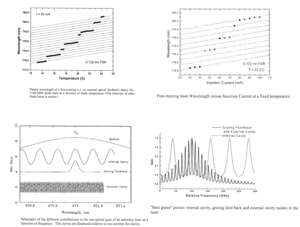
Fig. 13 Various attributes to mode hopping. Top two graphs indicating the available modes/wavelengths supported by close-to-constant current/temperature. Bottom two graphs indicate the gain of the internal and external cavity, and the grating feedback.#
Injection current changes the output wavelength of the laser. But various external factors can also cause the injection current/temperature to fluctuate, resulting in one kind of mode hopping.
Bottom left of the graph in Fig. 13 indicates that the external cavity has a closely packed profile of gain, similar to a sine wave, because spatially, assuming the treatement of light is a standing wave is appropriate, the back facet of the laser and the front facet of the external cavity form the boundaries of a standing wave. If the laser is lasing in IR range (1000 nm), a number as many as 300,000 nodes (of the standing wave) can exist in a mere 30 cm, and positioning the external cavity closer to or further from the laser can also result in changing the “boundary condition” of the standing wave, resulting in a very small change of mode in gain.
Once we have an idea how to work with the gain of a laser, then we know how to tune it, and can then begin with the experiment.